And this has been, roughly, the least-covered topic photographically and structurally in the history of train and locomotive documentation.
I don't quite understand why; it is something I try to mitigate on my blog when I can.
With that in mind:
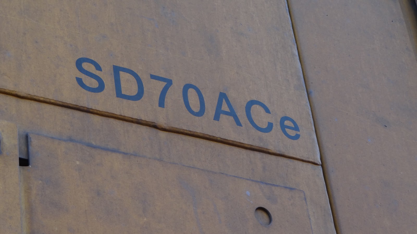
EMD's SD70ACe (the "e" stands for "enhanced") began its life in April of 2003; there are now over 1,400 built.
The SD70ACe is very similar in appearance to the Phase II "true" 6,300-hp SD90MAC locomotive, a dual turbocharged four-stroke diesel (1,010 cubic inches per cylinder):

Above, I captured an H-engined Phase II SD90MAC #8536 (Note any similarities to the SD70ACe?) in January of 2003 as it passed what train crews know as "Rocky Point."
This location, also called "American," sits roughly 1,200-feet above the north fork of the American River.
In fact, Southern Pacific established a formal platform and train stop (near MP 161) at this point in 1916, where passengers could step off and marvel at the depth of the gorge and the view to the west towards Sacramento. This train stop ceased in 1918 because of WWI.
You can extensively search physically (as have I), but no remnants whatsoever remain of this platform. I can tell you, however, from personal experience, that on a good night anyone can look down the "V" of the cut, to the west, and see the lights of the Sacramento Valley many, many miles below. It's a wonderful view and quite impressive. That said:
On the SD90MAC above, note the squared-off cab, the rectangular windows (similar to GE locomotives, now), the electrical cabinets and flared radiator housings with extended dynamic-braking tail. You can see how EMD took these traits and incorporated them into their most recent mass-production AC freight locomotive, the SD70ACe. The ACe is 74-feet long, with a two-stroke engine. The H-engined SD90MAC was 80-feet long, in a four-stroke.
EMD's SD70ACe was the builder's answer to Tier 2 emission requirements. EMD believed that a reworked engine -- that was familiar to shop crews worldwide -- would help sell the locomotive due to the foundational and reliable 710G3C-ES 16 cylinder prime mover. This 710 engine, delivering 4,300 horsepower, required only some slight modifications to ensure emission compliance.
But there's more: EMD ensured that all electrical wires are on the right side of the locomotive and all piping is on the left, with most pipes and wires routed under the frame and potentially serviced by a man standing outside the engine -- as opposed to someone crawling around the bottom of the engine room.
AC-driven power has become popular with Union Pacific -- though locomotives with AC cost more money -- because these units can be horribly lugged at low speeds with completely-pegged ammeters. AC motors offer higher starting tractive effort. AC motors are also more reliable and simpler than DC motors -- but the cost comes in terms of requiring expensive inverters to generate a variable-frequency AC signal.
With that, let's explore the cab of UP's 8548, an EMD SD70ACe, first by video:
[Please click on the link above to watch the video in its full size; I've yet to figure out how to re-size a YouTube video into the New Blogger, so information is cut out. Also: play with headphones.]
With regard to the below photographs, you can click on each one to enlarge and then copy to your desktop. If you reproduce in any fashion, I grant permission as long as I am credited.

Right side of unit. Fuel fill and fuel shutoff on this side.

Flared radiators for assisted cooling.

Rear of unit.

Rear of unit with flash. Note sand fill covers for rear truck sanding.

Sand cast solid steel trucks, the HTCR-4 radial variety.

Note massive shock absorbers. Accordion-like device is traction motor blower.

Close-up of traction motor. Quite unsettling to shoot this, as locomotive was active and idling. Had to stick my head and camera under the loco in a precarious position.

Very thick cables transferring power from generator to traction motor below. You can also see the brake shoe to the right of the wheel. Each of these traction motors weigh 6,000 pounds.

Flash shot of front of SD70ACe.

Detail of UP wings and ditch lights.

Detail of pilot, knuckle, connecting cables, air hose and pin bar.

I must say, I very much enjoy seeing the revitalized UP wing logo.

Number panel, window shield and sliding window on conductor's side.
UP's model tape.

Piping down the left side of the locomotive. More accessible for maintenance.

Left side of engine.

Left side of engine with flash. Note the huge electrical inverter room behind the cab.

Locomotive manufacturers are moving from the "desktop" paradigm to the original AAR "control stand" type.

Control cluster. To be examined in detail.

Overall view of Conductor's side of cab.

Conductor's chair, along with the "third" seat in the cab.

Engineer's position, on the right side of the cab. Note the holder for the throttle handle, as well as small desk area for paperwork.

Detail of (top to bottom) dynamic brake, throttle, and reverser.

FAR radio head above, WABTEC braking module below. Train brakes above with red handle; unit (independent) brakes below. Application to the right; release to the left.

Left computer screen, displaying mph, brake pipe pressure, status of units.

Panel commanding headlights and interior HVAC conditions.
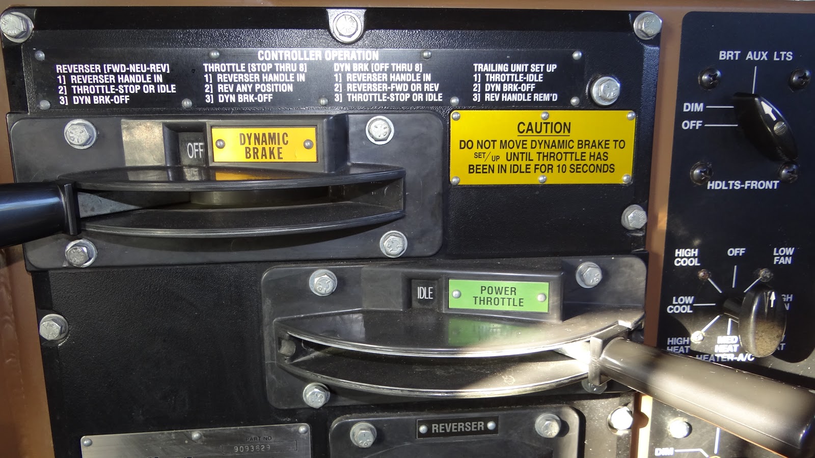
Detail of dynamic brake and throttle. Read the "controller operation."

Detail of sanding operation. Check out the welding quality on the vertical left.

Detail of the reverser position.

Detail of the throttle controller on the left-situated FRA stand. Note the large hex-head bolts attaching various controls to the stand itself. This makes for more easier removal and access.

Horn and Alerter reset button. Again, note the rather coarse welding to the right of the radio head. You can see that this control stand is created from scratch. Also, this control stand is taller than those in a new GE locomotive, such as the C45ACCTE. It tends to more greatly occlude the view from the engineer to the conductor.

Conductor's side of EMD cab.

Conductor's seat, top, and third seat in the middle of the cab. Very heavy duty brown vinyl. And quite comfortable with many adjustments, I might add.

View out the engineer's side.

Engineer's view with some -- ahem -- toilet packets.

Conductor's view with same.

View to the rear of EMD SD70ACe, on engineer's left side.

Close-up of conductor's console. Left to right: speedometer readout, emergency brake handle, horn and radio microphone in holder.

First door from the cab forward. Toilet to left. Electronic controller rack to right.

View from conductor's side, to the right.

Same, slightly different.

Detail of conductor's desk: speedometer readout, emergency brake valve, horn, radio mike.

Two different foot-rests on conductor's side of cab, bottom. With various electrical conduit pipes.

Door to nose of cab.

Back wall of cab with collision strut.

Overall back wall of cab, with view towards conductor's right side.

Geek Squad flow chart for fixing obscure stuff that crews couldn't care less about.

Right side engineer's seat.

Engineer's side footwell, to include three foot-rests.

Engineer's overall controller view from seat.

Same view, slightly different angle.

Major control panel, including start switch, locomotive isolation switch, lights and dynamic brake position cutout.

Geek chart and lower cab filter cover.

Here is an "extra" fold-down jump seat for a potential "fourth member" of the cab. Adjacent right side cab door. Floor, by the way, is a spongy type rubber for cushioning and insulation/sound damping.

Middle chair, covered -- as are the others -- with heavy duty vinyl and bolsters.

Conductor's side chair, vinyl, adjustable, with armrests.

View out center of cab.

View towards right side cab door.

Engineer's AAR control stand on left and screens to front.

Overall view of conductor's side of cab.

View of engineer's position from above.

Air Start system.

Loco ratings and information.

8548's rating.

Close up of isolation switch.

Same, different angle.

Left computer screen.

View out right side locomotive door.

Detail of right side loco door.

Detail of master screen.

Controller information.

More controller information, detail.

Radio above, brakes below.

Radio head above; brake controller below with red and black handles. Train brakes: red. Independent: black.

High view from the engineer.

Engineer's view with screens below.

Left side conductor's view.

Left side conductor's view behind, in mirror.

This is MP154 in the cab.
I hope you enjoyed this excursion into the cab of an EMD SD70ACe locomotive. As per normal, no information will be given or revealed about the time, date or location of each cab visit, or the employees who were so kind as to allow me access to same.
MP154


